Ontario Provincial Board of Health Annual Report 1909 pg. 90
by John Galt, C.E.
In accordance with your instructions received in December, 1908, I have made a study of your local conditions in respect to an efficient sewage disposal system for Palmerston, and after investigating the subject thoroughly, both as to present conditions and with a view to possible future necessities. I beg herewith to present my conclusions and recommendations, accompanied by complete plans, illustrating my ideas and proposals.
Local Conditions Bearing on the Problem
It will be in order to state briefly the situation at Palmerston and the local conditions, which have a bearing on the question of sewage disposal.
The population, according to the latest Government return, is 1,948. Local authorities estimate it to be somewhat larger than this, but for all practical purposes it may be taken as about 2,000.
The town is served in part by a sewer system constructed of about 9,000 feet of vitrified tile pipe, ranging in size from twenty inches diameter on the main outfall to ten inches diameter on residential streets.
The system is designed to take both house sewage and a certain amount of surface drainage, but up to the present time it has been used chiefly for cellar drainage, and lor the purpose of draining surface water from the low-lying portions of the town site.
I have also found that 95 houses are at present contributing sink waste to the sewers, and the drainage from the G.T.R. shops and round house is also delivered to the sewers. About 30 catch water basins are provided on the streets to take surplus water during rains.
The various manufacturing concerns, viz., O’Mara’s pork factory, L. H. Clark’s malt house, Watt’s oatmeal mill, and Meyer’s flour mill, do not use the sewers, and, owing to lack of necessary fall, it is not likely that they will use them. Their drainage is now taken off in a northerly direction, and I therefore do not think it will be necessary to consider the presence of trade waste in the sewage, except that received from the G.T. Railway’s round house and shops. This latter will probably carry very little waste matter, being largely the result of boiler washings very much diluted and having a certain amount of waste oil in it.
Palmerston is now supplied with a water system, comprising about 15,000 feet of water mains, which extend over the greater part of the built-up portions of the place. From the above it will be noted that the water mains cover about 70 per cent, more territory than the sewers at the present time, and it is to be expected that the future extensions of the sewers will be in the territory now served by the water works.
The outlet of the sewer discharges into a small stream which runs through a flat, marshy valley for three miles, to the point where it empties into a branch of the Maitland River.
The grade of the sewer outlet is only one and a half feet above the level of the water in this stream, and there is no natural fall at this point or elsewhere along the stream sufficient for the operation of complete sewage works. This will, therefore, have to be provided as explained later in this report.
Population to be Provided for
This point was carefully investigated, and it was found that the sewers now laid serve 206 houses containing a population of 804 persons. The territory served by both water mains and sewers has in it 269 houses and 1,137 people.
As previously stated, the extensions of the sewers will undoubtedly follow the water mains as at present laid, and it will likely be some years before this whole territory is sewered.
In my present judgment, therefore, I consider it will be sufficient at the present time to provide sewage disposal works of a capacity ample for 1,200 of the population, due allowance being made for the additions to the sewage flow resulting from the G.T.R. waste, storm water and surface drainage.
Quantity of Sewage
By gaugings made at the mouth of the outlet sewer it was found that the average flow now is at the rate of 100,000 gallons per day. Further investigations indicated that the total quantity was contributed from the following sources: —
| G.T.R. round house | 45,000 gals. per day |
| House sinks | 20,000 gals. per day |
| Land drains | 35,000 gals. per day |
| Total | 100,000 gals. per day |
I have assumed that 1,200 people, when properly connected to the sewers, will contribute at the rate of 75 gallons per capita per day, an amount of domestic sewage = 75 x 1,200 = 90,000 gallons. Deducting the amount now contributed by them, viz., 20,000 gallons, the total quantity of sewage to be provided for by the works will be 100,000 + 70,000 =170,000 gallons daily. This sewage, being very much diluted by large quantities of water having little organic pollution, will in consequence be a weak sewage, carrying, I anticipate, about sixteen parts of suspended solids per 100,000 parts of sewage.
Fall Necessary for the Works
As has been previously pointed out in this report, scarcely any natural fall is available at the sewer outlet, and this will have to be provided in one of two ways, viz.. either by pumping the sewage to higher ground adjacent to the creek, or by deepening the creek channel sufficiently to give enough grade fall throughout the works.
The plans for a drainage ditch through this territory, already submitted to the Council of Palmerston, have been studied relative to the requirements of the proposed works, and it is found that the depth of the ditch as proposed (viz., three feet) is not sufficient for the purposes of complete disposal works, and it will be necessary to deepen the last mile of this ditch and obtain at the sewer outlet a depth of cutting amounting to over nine feet. Comparing the two methods of operation, i.e., gravitation or pumping. it is very evident that the deepening of the ditch is in the main by far the cheaper proposition. The cost of pumping plant and annual pumpage, capitalized at the usual rate of interest, would be greatly in excess of the annual interest on the expenditure made in deepening the ditch.
I therefore advise you to deepen the ditch as shown by the revised grade on the profile referring to this part of the scheme. The calculations of the comparative cost are based on a ditch three feet wide in the bottom and having one and a half to one slopes on the sides. It is possible that the ditch would stand with one to one slopes, but the flatter slopes would doubtless be the most satisfactory in the end, and it has accordingly been adopted as the basis for the estimates of this part of the works.
Disposal Works
The creek which will conduct the effluent through three miles of farms before it empties into the branch of the Maitland River, maintains a small flow of water during the greater part of the year, but in the summer seasons sometimes becomes nearly dry.
The water of this creek is, I understand, used by the residents along its banks for the watering of stock. For that reason, and also from the fact that the flow of the Maitland branch is not large and would be easily polluted by sewage, it is evident that your disposal works should procure a sewage effluent both organically and bacteriologically pure. To obtain this result I propose to pass the sewage first through liquefying tanks; secondly, through intermittent sprinkling filters; lastly, through a sand filter.
The works are designed on the basis of a daily dry weather flow of 170,000 gallons, made up as follows: —
| Domestic Sewage | 90,000 |
| Trade effluent, G.T.R. shops | 45,000 |
| Farm drains | 35,000 |
| 17,000 |
Owing to the large amount of dilution from the G.T.R. and farm drains this will be a weak sewage, and I have estimated that about three-quarters of the G.T.R. sewage and all of the farm drains may be allowed as dilution, leaving practically 101,000 gallons as requiring nitrification by the filters. The works are calculated to take care of an amount of storm water equal to three times the dry weather flow.
Description of Works
The sewage will first enter a screening chamber 10-ft. x 10-ft. x 8-ft. deep. This chamber is provided with a screen to keep back inorganic solids and refuse. It then passes into a storm overflow chamber, provided with iron pipe, permitting all storm water over and above three times the dry weather flow to pass to the storm water basin. The excess storm water, after it has settled in the basin, is permitted to flow out into the creek.
The sewage up to three times the dry weather flow is passed into the liquefying tanks.
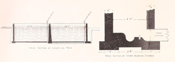
Liquefying Tanks
The tanks have a capacity of 170,000 gallons, or one day’s dry weather flow, each having a capacity of 85,000 gallons. They are in duplicate, to permit of cleaning and repairs. The floor is sloped, having eight feet of sewage at the inlet and six feet at the outlet. This is for the purpose of keeping the sludge concentrated at one end, from where it may be removed partly with sludge drains and partly by sludge pumps.
They may be operated as continuous flow, sedimentation tanks or as septic tanks.
If as the former, sludge must be removed frequently; if as the latter, sludge should be removed at periods of about four months.
When septic action is maintained, it is estimated 25 per cent, of the organic solids will be digested.
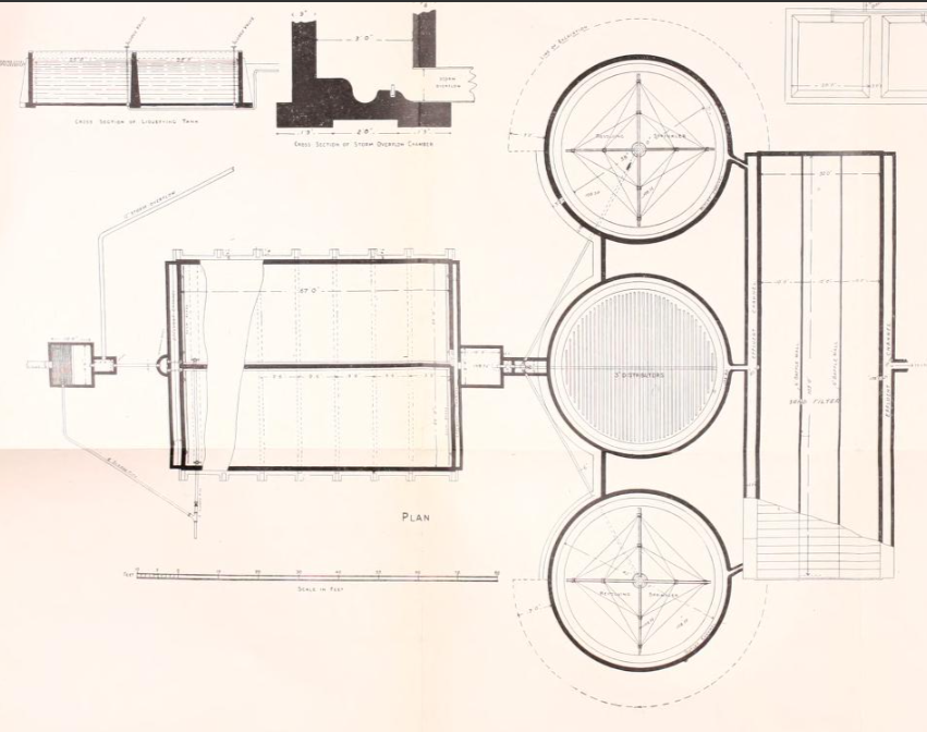
Percolating Filters
The effluent of the tanks is distributed on to three sprinkling filters, each being forty feet in diameter and five feet deep, and collectively having a total of 700 cubic yards of filtering media. They are calculated to take the sewage at the rate of 145 gallons per cubic yard per day, and in this due allowance is made for three times the dry weather flow during periods of rainfall.
The discharge to the filters is controlled and regulated by a dosing chamber and syphon. This chamber is 10 x 6 x 1-ft. 6-in. deep, and permits regular and equal quantities to be discharged on the filters, of an amount equal to two gallons per square yard of filter. This appliance is to prevent over saturation and the occurrence of hydraulic head, which would tend to flush the filters. The sewage will be distributed by three revolving sprinklers, operated by the sewage under a head of 1-ft. 6-in.
It is anticipated that these revolving sprinklers cannot be operated successfully during the coldest weather of the winter, and I have provided an alternative method of distribution for that period. As shown by the plans, the sewage will be taken through a second set of pipes and distributed through open-jointed three-inch tile placed about six inches under the surface of the bed. The filtering medium will be composed of hard burning clinker, ranging in size from half to one inch, the outer circumference to be sloped up with larger pieces of the same material.
Collecting drains of three-inch open-jointed tile will be placed on the concrete floor and radiating to the collecting channel. A retaining wall is provided about the sprinkling filters, adjacent to the tank, permitting all the pipes, valves, etc., to be placed underground and thus protected from frost. For the purpose of aeration the filters themselves are left exposed, but should the need arise, temporary winter coverings could be easily provided with the proposed arrangement.
The above process should produce an effluent free from organic matter and non-putrescible. It is not calculated, however, that many of the bacteria will be removed, and the effluent will be biologically unfit for the use of man or cattle. Further treatment is, therefore, considered to be necessary.
Sand Filter
I propose to remove the bacteria by passing the effluent from the sprinkling filters through a sand filter.
As there is insufficient fall for down word filtration, submerged or upward filtration is advised. By this method the liquid will be conducted to the bottom of the filter by a special chamber, and be directed up through graded sand to the outlet, and delivered into the creek. The bottom of the filter bed will be laid with coarse material, allowing the liquid to spread uniformly over each section. The sand will be above this, and above the sand coarse gravel will be used to keep the sand in place. The filter will be 103-ft. X .30-ft. X 2-ft. 6-in. deep, and is calculated to work at the rate of two and a half millions per acre daily.
The walls and bottom will be of water-tight concrete, and the top provided with a movable wood cover built in sections. This cover will be used in winter to keep out frost, and removed whenever weather conditions will permit. The efficient resulting from the combined processes can be discharged into the creek, and should be free from all organic pollution or pathogenic organisms.
Storm Overflow
At certain seasons an excess of storm water over and above the amount designed for the disposal works will overflow at the overflow chamber. The dilution at such periods will be so great that this overflow will carry very little sewage, and it might perhaps with safety be delivered directly to the stream., but it will probably be better to arrest it for treatment.
In many sewage plants the storm overflow is spread upon the land and allowed to filter through the soil. The sub-soil at Palmerston being blue clay, with very little loam upon it, does not favour this method. Under the circumstances, I would advise settling the excess storm flow in a large sedimentation basin, with a capacity of 500,000 gallons, before emptying it into the creek. This basin could be excavated in the clay, and would not require any concrete. The lower end should be provided with pipe and valve, to facilitate draining at the proper time. The basin could at any time in the future be made into a roughing filter, by filling the excavation with coarse filtering media, should the storm flows require a more complete treatment.
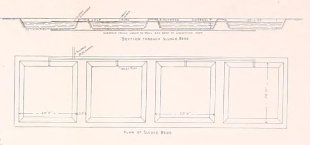
Sludge Disposal
It is now an acknowledged fact that liquefying tanks, when operating at their best, will accumulate about 2.5 per cent, of the organic solids of the sewage, as well as a certain amount of grit and detritus not arrested by the screening chamber. The removal of this deposit or sludge from the tanks and screening chamber requires that some special provision should be made for this purpose, and also for the proper disposal of the sludge itself.
As there is very little fall on the site of the works, it will not be possible to drain much of the sludge from the bottom of the tanks through pipes. Pipes and sludge valves, however, are provided, which will admit of lowering the head of the sewage in the tank to some extent, at the same time driving out a portion of the sludge from the bottom. It is likely that the major portion will have to be removed by pumps or other method.
It is important that the sludge removed should not be deposited in the stream or elsewhere where it will be a nuisance and danger. Sludge beds have been provided close to the septic tank, upon which the sludge must be deposited, where it will drain and become, after a short period, of such consistency that it can conveniently be hauled on the land as a fertilizer.
The bed is divided into compartments containing coarse gravel underlaid with drains. These drains lead to a sump well, from which the drainage from the beds is pumped back to the tank to proceed through the regular course of purification. The drains from tanks and screen chamber deliver on to the sludge beds. The sludge, on drying sufficiently, can be dug out of the beds and used for tillage. It is considered that two compartments of the sludge bed will be sufficient for the first installation, and the estimate for it has been made accordingly.
General Remarks
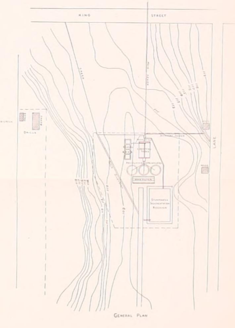
The amount of land required for the work as shown upon the general plan is three and a half acres. Sufficient has been taken to admit of duplicating the works at some future time. In the mean time the spare land can very well be used for tillage, using the sludge from the tanks for fertilization. Very little of the excavated materials will be needed for banking or mounding on the works, owing to the fact that the level nature of the site puts all the work in excavation. In consequence, a portion of the excavated material will have to be removed from the site, and it may be profitable to provide sufficient land to deposit this upon and thus save extra expense entailed by carting the material for some distance.
From a study of the plans and the site it will plainly be seen that the first important work of construction towards the installation of the disposal works will be the deepening of the drain from the branch of the Maitland River to the site of the works. Until this is accomplished, no work on the system proper fan be economically carried out, owing to the saturated condition of the ground. The deepening of the ditch will require some time, as the last mile alone, on which the grade will be lowered with slopes at one and a half to one, will require the excavation of 17,000 cubic yards of material. With slopes at one to one on the sides it will require the excavation of 12,000 cubic yards of material.
In the estimate of cost we have taken the extra cost of excavating the last mile as the total cost less the cost of ditch first proposed. Both ditches are assumed to have slopes at one and a half to one on the sides, and to be three feet wide on the bottom.
In the estimated cost of the works, which is herewith appended, I have considered the various parts of the work in detail, and all usual expenses have been taken into account. The system has been designed to perform the work of purification thoroughly, and necessarily must be somewhat expensive owing to the lack of natural conditions which would favour the construction of an efficient and proper works.
I trust the report and plans will be clear to you, and I shall await your further wishes in the matter.
Summarized Estimate of Cost
| 1. | Sewer Manhole and connecting sewers at manhole | $36.00 |
| 2. | Screening Chamber | 155.00 |
| 3. | Overflow Chamber | 46.00 |
| 4. | Pipe Connection | 5.00 |
| 5. | Liquifying Tanks | 2,787.60 |
| 6. | Dosing Chamber | 52.00 |
| 7. | Syphon Chamber and Syphon | 43.00 |
| 8. | Valve and Pipe Chamber | 40.00 |
| 9. | Sprinking Filters, Piping and Distributors | 4,351.00 |
| 10. | Sand Filer | 2,483.00 |
| 11. | Sludge Beds | 300.00 |
| 12. | Storm Water Basin | 1,028.00 |
| 13. | 3 1/2 Acres of Land at $75,000 | 262.00 |
| 14. | Deepening Drain | 2,200.00 |
| 13,798.60 | ||
| Add 15% for contingencies | 2,069.40 | |
| 15,868.00 |